
As Kubernetes clusters on Amazon EKS grow in scale, the default AWS VPC CNI—which relies on EC2 ENI and IP address limits—often becomes a constraint for modern, high-density workloads. These limitations push platform teams to look for more scalable and flexible networking models.
To overcome this, many organizations are adopting Cilium as the primary CNI on AWS EKS with ClusterPool IPAM and overlay networking. By fully replacing the default CNI, Cilium removes dependency on ENI-based pod IP allocation, enables predictable IP management at the cluster level, and supports faster, more reliable scaling.
In this blog, we discuss installing Cilium as the primary CNI using ClusterPool IPAM on EKS and explain why this setup is widely adopted by enterprises building scalable, future-ready Kubernetes platforms on AWS.
Video on Cilium Standalone on AWS EKS with ENI IPAM and Native Routing
In case you want to refer to the video, then here is my video (disclaimer: I have used AI-voice over to avoid MTI from my accent)
Why use Cilium in EKS ClusterPool IPAM
Limitation of ENI Datapath and IPAM
Before we begin to check the ENI limitations, let’s first discuss how a Pod gets an IP in ENI mode. When we create a pod schedule request, the Kube-let calls the CRI, and then the CRI calls the CNI to request an IP. Then, the Operator makes an API call to retrieve a batch of IPs—usually 12 to 15 at a time this is to populate the IP pool fields in the CRD. The Agent then reads CRD and provides an IP back to the Kube-let, allowing the Pod to be scheduled.
As you can see in the diagram (refer FIG. A), the node uses the Primary IP of the ENI, which becomes eth0 and is used as a cilium host. Meanwhile, the Pods grab those available Secondary IPs.
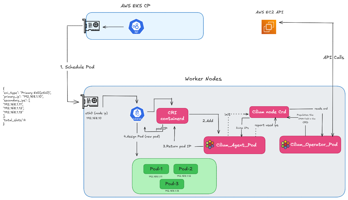
FIG.A: how we get ip using eni ipam
But what happens when we run out of Secondary IPs on the primary eni?
One thing is happening here: when the Cilium Operator asks for a new batch of IPs, if we don’t have enough available slots for secondary IPs on the primary ENI, EC2 automatically attaches a new ENI. So, in ENI mode, these additional Pod IPs come directly from the Secondary IPs of this newly attached ENI. Once that new ENI is attached and the IPs are available, the pending Pod is created.
However, in a real cluster, you generally won’t see a Pod stuck in a ‘Pending’ state while this happens. Because the Operator requests a batch of IPs ahead of time. So, this ENI attachment triggers before we completely run out of addresses. These newly attached IPs are kept as ‘warm IPs’. So, this process happens in the background, ensuring that an IP is already available by the time the Pod needs to be created.
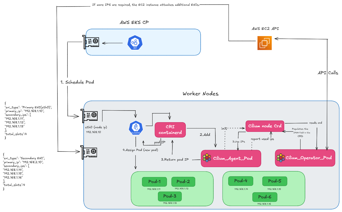
FIG.B: how we get ip using eni ipam by attaching additional eni
However, this scaling isn’t infinite. Now, as you can see in the diagram (refer FIG.C), we have attached another ENI to get more IPs, but we have now reached our max limit. Every instance has a limit on how many ENIs can be attached. Since we have hit that cap, we physically cannot attach any more interfaces, and therefore, we cannot create any new pods.
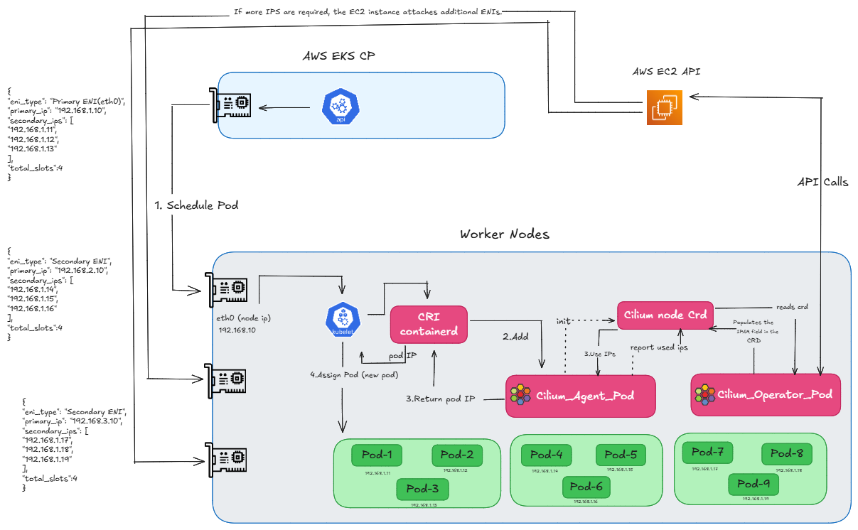
FIG.C: how we get ip using eni ipam by attaching multiple enis
So, we can say that the CNI manages Secondary IPs for Pod IPs, and Cilium in ENI mode uses these Secondary IPs. And that is exactly what causes our limitations in ENI mode. The problem is that every EC2 instance type has a limit on how many ENIs and IPs it can use. For example, if we take a t3.small instance, it allows 3 ENIs, but each ENI only supports 4 IP slots—primary and 3 secondary—so we can have only 9 application pods. So, in the end, we can say that because of these ENI limits, the Pod count is directly limited by the physical capacity of the EC2 instance.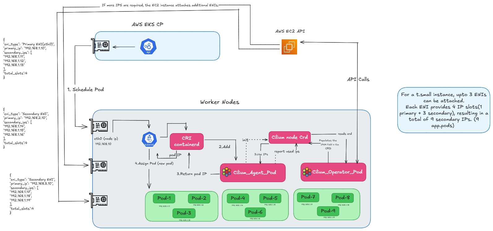
FIG.D: how many enis can be attached
Now, how do we fix this? And how do we use more IPs? This is where our ClusterPool comes in.
Use of ClusterPool IPAM
As we have discussed in our routing videos, the Cilium Operator will populate the Cilium Node CRD with IPs from the podCIDR flags. So, we can simply pass CIDRs to the pods, solving the allocation problem.
But now, the problem is how can we route them. In AWS, we have routing tables for the ENI IPs, and we use native routing mode. But here, AWS doesn’t know about our new Pod IPs. So, how will we route our traffic? This is where the tunnel comes into the picture. We just created a node-to-node tunnel. So, for ClusterPool to work, we don’t need complex networking—just a tunnel and the IPs we are passing.
Now, you can see the config map fields:
- clusterPoolIPv4PodCIDRList is set to a custom CIDR of 10.200.0.0/16. This represents the entire cluster, Pod CIDR.
- clusterPoolIPv4MaskSize is set to 24, which is the mask size assigned for each Node.
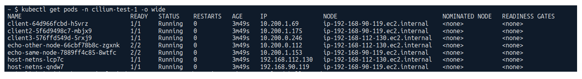
And when you take a look at the screenshot below, you can see, my Node IP is on a completely different CIDR (192.168.x.x) which comes from the AWS ENI. But for the Pods, we have a different CIDR entirely—you can see all the pods are running with 10.200.x.x addresses.
Below (refer FIG.E), you can see that while the node’s eth0 IP still comes from the ENI’s Primary IP, for Pod IPs we no longer call the EC2 API. Instead, the Operator reads the Pod CIDR range from the Config Map and assigns those IPs directly to the pods.
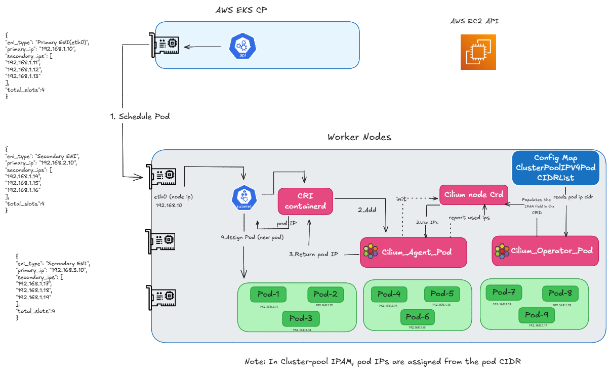
FIG.E: how we assign ip using clusterpool
And that concludes our ‘Why ClusterPool‘ part. Now, let’s move to the next section and discuss the requirements.
Prerequisites and requirements for ClusterPool
1.General requirements
Ensure correct kernel version, required IAM roles, supported instance types and proper VPC/Subnet configuration.
2. Disable Default AWS Add-ons
Disable AWS-node (AWS VPC CNI) and any other CNIs to avoid conflicts with Cilium.
3. Enable Private Networking
Add private Networking: true in the node group configuration.
4. Add Cilium Startup Taint
Use the taint node.cilium.io/agent-not-ready=true:NoExecute so application Pods only start after Cilium is ready.
Next, let us move to the step-by-step installation.
Step-by-step installation of Cilium on AWS EKS using ClusterPool IPAM
1.Create the cluster
Apply cluster configuration
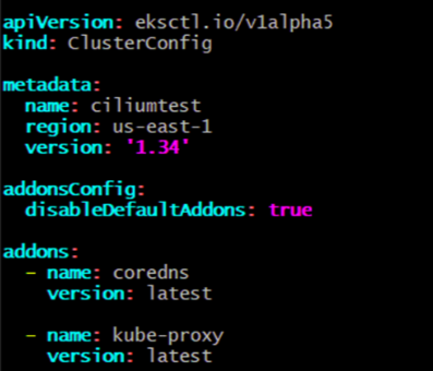
Create the EKS control plane using an eksctl cluster configuration file. In this configuration, default AWS add-ons are disabled to avoid conflicts with Cilium.
Create the cluster using the configuration file:

If you need to tear down the cluster:
 Apply node group configuration
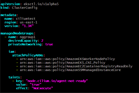
Next, configure the managed node group with settings required for Cilium, including private networking and start-up taints.
2. Apply Helm charts
Once the EKS cluster and node groups are ready, install Cilium as the primary CNI using Helm. In this setup, ClusterPool IPAM is used to allocate Pod IPs from a dedicated CIDR range instead of relying on AWS ENIs.
Install Cilium using Helm
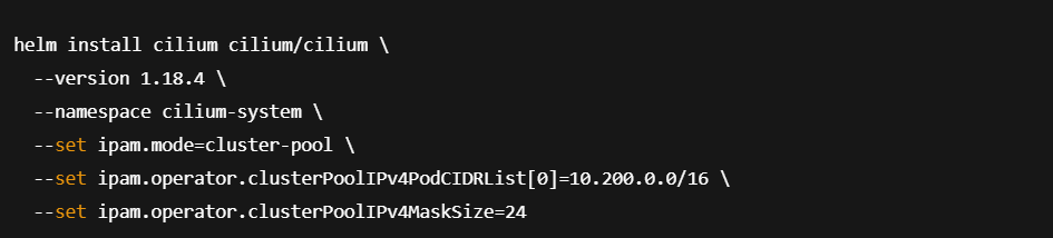
To configure multiple CIDR ranges:

Perform connectivity tests
After installing Cilium, validate the networking setup using Cilium’s built-in connectivity test suite.

A successful test confirms that Cilium with ClusterPool IPAM and overlay networking is functioning correctly across the cluster.
Final Thoughts
Using Cilium with ClusterPool IPAM on AWS EKS is a powerful alternative to the default ENI-based networking model. It removes AWS IP scaling constraints, simplifies cluster growth, and unlocks advanced capabilities such as eBPF-based networking, observability, and security. For teams running large or fast-growing Kubernetes clusters, this architecture provides a future-proof, scalable foundation without sacrificing performance or reliability.
If you’re planning to adopt Cilium in production or need expert guidance, reach out to our Cilium experts.