As production clusters scale, teams increasingly move toward VPC-native networking and high-performance datapaths, where the way traffic is routed and how IP addresses are allocated directly affects latency, scalability, and operational cost. In this context, Cilium’s routing modes and IP Address Management (IPAM) are no longer low-level implementation details—they are core architectural decisions that define how reliably and efficiently Kubernetes workloads communicate at scale. In this blog, we dive deep into Cilium routing modes and IPAM and explain how to choose the right model for production-grade Kubernetes networking.
Video on Cilium Networking Concepts
In case you want to refer to the video, then here is my video (disclaimer: I have used AI-voice over to avoid MTI from my accent).
Cilium routing mode on AWS EKS
Concept of routing in Kubernetes
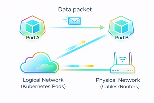
- Routing determines the path a data packet takes to travel from Pod A to Pod B. (refer FIG. A)
- It bridges the gap between the logical network (Kubernetes Pods) and the physical network (Cables/Routers).
Challenge we face while routing
- Since Pods are ephemeral and constantly changing their IP addresses, your physical network usually has no idea they exist due to which traffic will be not able to reach the destination Pod.
- ‘Where to send the package?’- such concern arises (refer FIG. B)
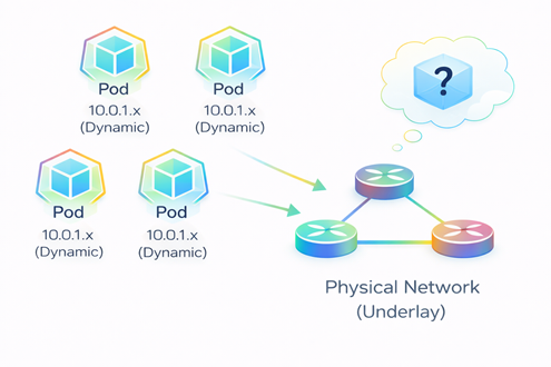
FIG. B: Pods on different nodes communicating across a physical network.
How Cilium solves the routing challenge
Cilium solves this challenge in two ways
- Overlay mode (refer FIG. C)
- Native routing (refer FIG. D)
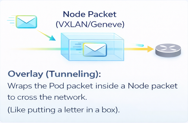
FIG. C: Packet transfer in Overlay mode
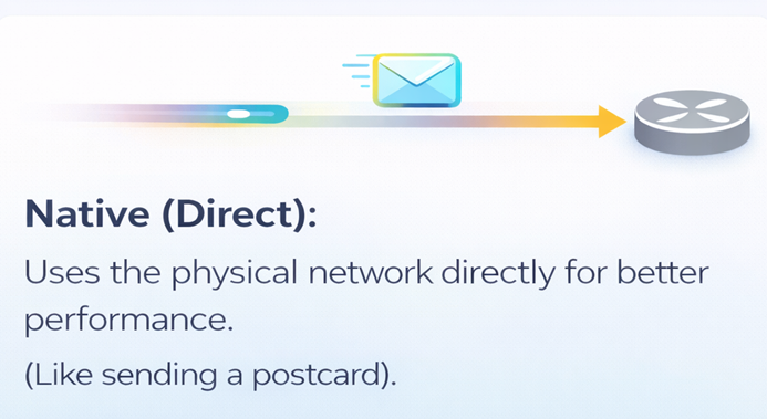
FIG. D: Packet transfer in Native routing
Routing modes in Cilium
Following are the 2 main types of Routing modes in Cilium based on the way of sending a package from one pod to another:
- Overlay Mode (Tunneling)
- Native Routing (Direct mode)
Routing mode1: Overlay mode (Tunneling)
As the name suggests, we use a tunnel between nodes to transport data. This is the default mode in Cilium, and quite honestly, it’s the easiest way to get started. Why? Because it requires zero changes to your existing physical network routers.
If you look at the diagram (FIG.E), you can see exactly what happens. When ‘Pod A’ on the left wants to talk to ‘Pod C’ on the right, Cilium doesn’t send the raw packet directly onto the network. Instead, it wraps that original packet inside a ‘tunnel’—usually using standard protocols like VXLAN or Geneve. To your physical network, this just looks like traffic moving from Node A to Node B, effectively hiding the internal Pod conversation. The network acts purely as a carrier. The big win here is simplicity.
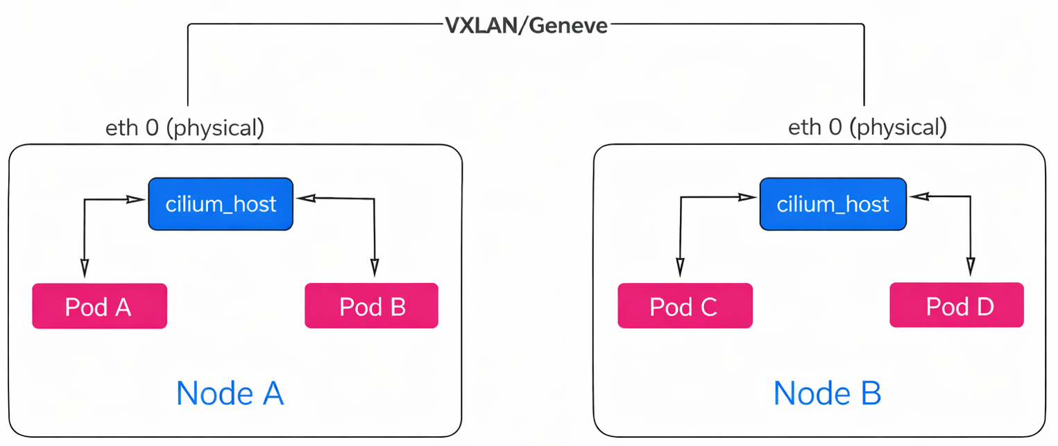
FIG. E: Data transfer using Overlay mode
Routing mode2: Native routing (Direct mode)
Now let’s look at our second option: Native Routing, sometimes called Direct mode. As the name implies, this mode removes the tunnel entirely.
If you compare this to the previous slide, you’ll see we are no longer wrapping packets in ‘boxes.’ Instead, packets are sent directly onto the network without any encapsulation overhead like VXLAN or Geneve. So, without a tunnel, how does the packet get from the Pod to the network? This is where Cilium is smart—it utilizes the standard routing capabilities already built into the host. Instead of handling everything itself, it delegates the job.
If you look closely at the bottom of the diagram (refer FIG. F)
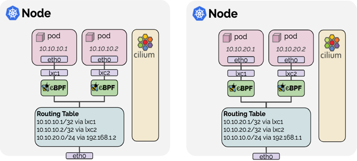
You will see the ‘Routing Table’ box. When a Pod (like 10.10.10.1) sends a packet, Cilium simply hands it over to the standard Linux Kernel routing table. You can see the rules right there in the image (FIG.F): 10.10.10.1/32 via lxc1. The Kernel sees this packet, checks its own routing rules, and treats it exactly as if it came from a local process running on the host itself. It then forwards the packet out through the physical interface (eth0) just like normal server traffic.
Now, this sounds great—better performance, no overhead. But there is a catch. Because we removed the tunnel, we can’t hide our Pod IPs anymore. This means your underlying physical network must be smart enough to know where every Pod lives. If your routers don’t know the Pod IPs, they won’t know where to send the packets.
Now, let’s look at how Overlay mode is different from native routing.
Overlay vs Native
- Overlay abstracts the network using tunneling, while Native routing removes encapsulation and relies on the underlay to route Pod IPs directly.
- Choose Overlay for fastest, no-touch setup; choose Native routing for maximum performance and cloud-native scalability.
Now let’s look at a special purpose datapath known as the AWS ENI Datapath which enabled when Cilium is run with the option —ipam=eni.
AWS ENI datapath
It is a special purpose datapath that is useful when running Cilium in an AWS environment. Pods are assigned ENI IPs which are directly routable in the AWS VPC. This simplifies communication of pod traffic within VPCs and avoids the need for SNAT. Pod IPs are assigned a security group. The security groups for pods are configured per node which allows to create node pools and give different security group assignments to different pods.
To understand how this works, let’s trace the packet flow using the architecture diagram (FIG.G).
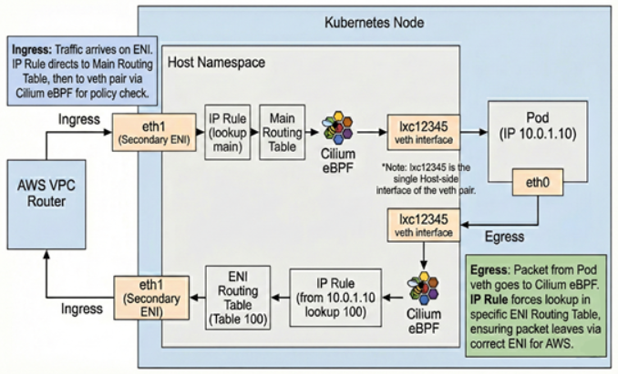
FIG.G: ENI datapath architecture
Let’s start with Ingress (Traffic coming IN). When a packet arrives from the VPC, it hits the Node on a specific network interface—in this case, eth1, which is our Secondary ENI.
The Linux Kernel receives this packet and encounters an IP Rule. This rule instructs the kernel to look at the Main Routing Table for any local traffic. The Main Routing Table has a direct mapping. It knows that this specific Pod IP is reachable via a virtual interface called lxc12345.
However, before the packet crosses that ‘virtual cable’ into the Pod, it is processed by Cilium eBPF. This acts as our policy enforcement point. It verifies if the traffic is allowed by your network policies. If permitted, the packet is delivered to eth0 inside the Pod.
Now, let’s look at Egress (Traffic going OUT). When the Pod sends a packet out, it travels back to the host. This presents a routing challenge: because the host has multiple network interfaces, we must ensure the packet leaves through the specific ENI that owns the Pod’s IP (eth1), rather than the system default.
To solve this, Cilium uses Source-Based Routing. As the packet reaches the host, an IP Rule examines the Source IP. It identifies that this IP belongs to ENI 1 and forces a lookup in Routing Table 100 (a custom table specifically for this ENI).
Routing Table 100 contains a default route that directs the traffic out through eth1. This ensures the packet returns to the network through the correct interface, preventing AWS from dropping it as spoofed traffic.
This architecture provides high performance and visibility because the Pod IP is preserved throughout the VPC (no SNAT is required). The trade-off is that you consume AWS IP addresses, which limits the number of Pods per node based on your EC2 instance type.
Now that we understand how packets travel, let’s see how they get their addresses in our next section i.e., IP Address Management (IPAM).
IP Address Management
IP Address Management (IPAM) is the process of automatically assigning, tracking, and managing IP addresses used by applications, servers, containers, and Kubernetes pods. In modern DevOps and cloud environments—where infrastructure scales up and down dynamically—IPAM ensures that every workload gets a unique IP address without conflicts or manual intervention.
Next, we will discuss about the various types of IPAM based on how the pods will get IPs.
IPAM types
- Cluster Pool
- AWS ENI IPAM
- Kubernetes Host Scope
- CRD-Backed
- Multi-Pool
Cluster Pool
Allocates pod IPs from a pre-defined cluster-wide CIDR, independent of the underlying cloud network.
AWS ENI IPAM
Assigns pod IPs directly from AWS VPC subnets using Elastic Network Interfaces for native cloud integration.
Kubernetes Host Scope
Limits IP address allocation to individual nodes, simplifying management but reducing cross-node flexibility.
CRD-Backed
Uses Kubernetes Custom Resource Definitions to declaratively manage and observe IP address allocation.
Multi-Pool
Enables multiple IP pools to support different workloads, environments, or network requirements within the same cluster.
Best practice of choosing the IPAM type
Choose the IPAM mode based on scale, performance needs, and cloud integration, while continuously monitoring IP utilization to avoid exhaustion.
Final thoughts
Understanding routing modes in Cilium—Overlay (Tunneling) and Native Routing—along with IP Address Management (IPAM) is essential for building secure, scalable, and high-performance Kubernetes networks. Overlay mode offers simplicity and portability across environments, while native routing delivers lower latency and higher throughput by leveraging the underlying network. Complementing these routing choices with the right IPAM strategy—such as Cluster Pool, AWS ENI IPAM, or multi-pool configurations—ensures efficient IP utilization and reliable pod connectivity at scale. By selecting the appropriate Cilium routing mode and IPAM configuration based on your infrastructure, performance goals, and operational complexity, platform teams can reduce networking bottlenecks, avoid IP exhaustion, and operate Kubernetes clusters with greater confidence.
In case you need help on adopting Cilium for your enterprise, you can reach out to our Cilium experts.